| CPC F01D 25/183 (2013.01) [F01D 25/125 (2013.01); F01D 25/162 (2013.01); F02K 3/06 (2013.01); F05D 2220/323 (2013.01); F05D 2240/54 (2013.01); F05D 2240/55 (2013.01); F05D 2260/213 (2013.01); F05D 2260/605 (2013.01); F05D 2260/98 (2013.01)] | 20 Claims |

|
1. A system comprising:
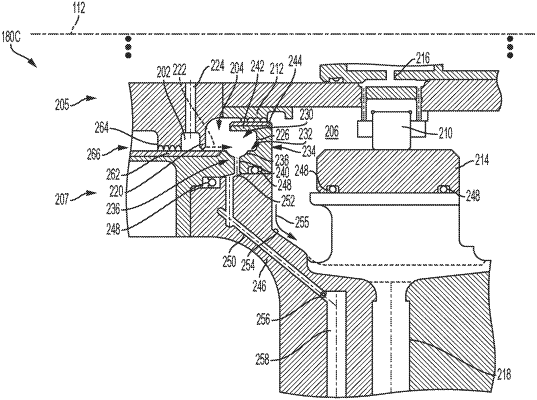
an air chamber comprising an inlet to receive pressurized air from a gas turbine engine;
an oil capture cavity positioned between the air chamber and an oil sump supplying lubricating oil to the gas turbine engine;
the oil capture cavity including an auxiliary vent formed in a base of the oil capture cavity;
a seal separating the oil capture cavity from fluid communication with the oil sump; and
a nozzle providing fluid communication between the oil capture cavity and the air chamber, the nozzle configured and positioned to regulate and direct a stream of the pressurized air into the oil capture cavity and against an opposite wall of the oil capture cavity, the opposite wall positioned and formed such that a flow of the stream of the pressurized air is directed to flow parallel to the opposite wall and circulate in the oil capture cavity back to the nozzle to form a cyclonic air flow in a non-rotational portion of the oil capture cavity and create a quiescent zone at the auxiliary vent.
|