| CPC B60H 1/3211 (2013.01) [B60H 1/323 (2013.01); B60H 1/3226 (2013.01); B60H 2001/3283 (2013.01)] | 19 Claims |

|
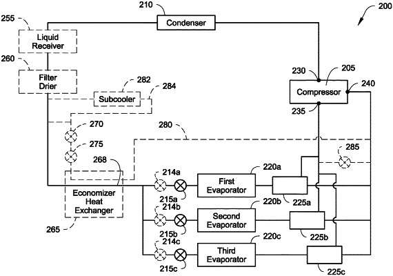
1. A climate control circuit for a transport climate control system that provides climate control to a climate controlled space of a transport unit, the climate control circuit comprising:
a compressor for compressing working fluid, the compressor including a discharge port that discharges working fluid out of the compressor, a main suction port that receives a first pressure working fluid, and an auxiliary suction port that receives a second pressure working fluid that is greater than the first pressure working fluid;
a condenser, downstream of the compressor, that releases heat from the working fluid into ambient air outside of the transport unit to cool and condense the working fluid;
a plurality of expansion valves, downstream of the condenser, each of the plurality of expansion valves controlling the amount of the working fluid directed to a corresponding evaporator of a plurality of evaporators;
the plurality of evaporators, each of the plurality of evaporators downstream of a corresponding expansion valve of the plurality of expansion valves, each of the plurality of evaporators absorbs heat from a different area of the climate controlled space to heat and evaporate the working fluid;
a suction flow control device downstream of each of the plurality of evaporators, wherein the suction flow control device includes a valve arrangement that is configured to direct the working fluid from each of the plurality of evaporators to one of the main suction port and the auxiliary port; and
a controller that:
determines whether each of the plurality of evaporators is operating to provide climate control within a fresh temperature range or operating to provide climate control within a frozen temperature range,
for each of the plurality of evaporators operating to provide climate control within the fresh temperature range instructs the suction flow control device to direct the working fluid from the corresponding evaporator to the auxiliary suction port,
for each of the plurality of evaporators operating to provide climate control within the frozen temperature range instructs the suction flow control device to direct the working fluid to the main suction port,
determines that each of the plurality of evaporators operating to provide climate control within the frozen temperature range has reached a set-point temperature, and
upon determining that each of the plurality of evaporators operating to provide climate control within the frozen temperature range has reached the set-point temperature, instructs the valve arrangement of the suction flow control device to direct the working fluid passing through each of the plurality of evaporators operating to provide climate control within the fresh temperature range from the auxiliary suction port to the main suction port.
|