| CPC B23P 17/04 (2013.01) [B23K 37/0417 (2013.01); B25B 11/02 (2013.01); B23K 37/0538 (2013.01)] | 7 Claims |
|
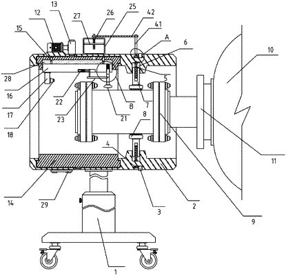
1. An assembling device for a rotating joint of rotary drying equipment, comprising a telescopic upright column (1), wherein a mounting sleeve (2) is fixed at a top of the telescopic upright column (1); gear rings (3) are movably mounted outside the mounting sleeve (2) in an embedded manner; one side of each gear ring (3) is engaged with a bevel gear (4); the bevel gears (4) are movably mounted inside the mounting sleeve (2) in an embedded manner; inner ends of the bevel gears (4) are connected with first screw rods (5); the first screw rods (5) are mounted in movement slots (6) through bearings; the movement slots (6) are formed in an inner wall of the mounting sleeve (2); the first screw rods (5) are sleeved with fixed rods (7) through threads; inner ends of the fixed rods (7) are welded with fixed plates (8); rotating joint bodies (9) are placed in the fixed plates (8); one end of each rotating joint body (9) is plugged into a flange cover (11) at an end portion of a rotary drying equipment body (10); a microprocessor (29) is fixed at a bottom of the mounting sleeve (2);
the assembling device further comprises:
a motor (12), wherein the motor (12) is fixed at a top of the mounting sleeve (2); an output end of the motor (12) is connected with a driving gear (13); a detection tooth ring (14) is engaged below the driving gear (13); the detection tooth ring (14) is movably mounted inside the mounting sleeve (2) in an embedded manner; the detection tooth ring (14) is located at a position on a left side of the fixed rod (7); an oil slot (28) formed in an inner wall of a top of a detection tooth ring (14) is internally connected with a detection seat (16) through a first elastic telescopic rod (15); a mounting plate (17) is fixed at a left bottom of the detection seat (16); a laser ranger (18) is fixed on an inner side of the mounting plate (17); an adjustment rod (20) is embedded into a right bottom of the detection seat (16) in an elastic sliding manner through a spring (19); an adjustment head (21) is integrally arranged at one end of the adjustment rod (20); the adjustment rod (20) is located between the fixed rods (7) and the laser ranger (18); an electric push rod (22) is fixedly embedded in a middle bottom of the detection seat (16); an output end of the electric push rod (22) is connected with a cross bar (23); one end of the cross bar (23) is located in a guide slot (24); the guide slot (24) penetrating therethrough is formed in the middle of the adjustment rod (20); and
an oil tank (25), wherein the oil tank (25) is fixed at the top of the mounting sleeve (2); a second screw rod (26) penetrating therethrough is mounted at a top of the oil tank (25) through a bearing; the second screw rod (26) is sleeved with a piston plate (27) through a thread; the piston plate (27) is located in the oil tank (25); openings penetrating therethrough are formed in a bottom of the oil tank (25) and in the tops of the mounting sleeve (2) and the detection tooth ring (14); and the openings in the bottom of the oil tank (25) and in the tops of the mounting sleeve (2) and the detection tooth ring (14) and the oil slot (28) formed in the inner wall of the detection tooth ring (14) interpenetrate each other.
|