| CPC B23C 5/109 (2013.01) [B23C 5/202 (2013.01); B23C 5/2213 (2013.01); B23C 2200/125 (2013.01); B23C 2200/164 (2013.01); B23C 2210/168 (2013.01)] | 2 Claims |

|
1. An end mill comprising:
a replaceable cutting insert including a rake surface having a substantially parallelogram shape, a bottom surface on an opposite side to the rake surface, a peripheral side surface extending between, and connecting, the rake surface and the bottom surface, a through hole extending through the rake surface and the bottom surface, and at an intersection ridge line at which the rake surface and the peripheral side surface intersect each other, a first main cutting edge and a first corner cutting edge are both formed,
the substantially parallelogram shape having oppositely positioned first sides and oppositely positioned second sides, and in a plan view of the rake surface, the first sides are longer than the second sides,
the peripheral surface including oppositely positioned first side surfaces that respectively correspond to the first sides of the substantially parallelogram shape and oppositely positioned second side surfaces that respectively correspond to the second sides of the substantially parallelogram shape,
the first main cutting edge is located at one of the first sides of the substantially parallelogram shape,
the first corner cutting edge is located at an acute angle corner of the rake surface and connected to the first main cutting edge,
the bottom surface including a first bottom surface that comes closer to the rake surface gradually toward the first main cutting edge when viewed from a central axis of the through hole in a first direction perpendicular to the central axis, and a second bottom surface that comes closer to the rake surface gradually toward a second main cutting edge opposite, and parallel to, the first main cutting edge when viewed from the central axis in a second direction perpendicular to the central axis, each of the first bottom surface and the second bottom surface being substantially one-half of the bottom surface,
the first bottom surface and the second bottom surface define respective first and second planes, a virtual intersection line is defined by an intersection of the first and second planes, and in a plan view of the bottom surface, the virtual intersection line intersects the central axis and is not parallel with the first main cutting edge; and
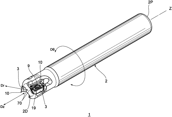
a tool main body extending along a rotation axis between a proximal end surface of a shank portion and a distal end surface of a cutting portion, the distal end surface being transverse to the rotation axis, the tool main body having an insert seat intersecting the distal end surface, the cutting insert replaceably fixed to the insert seat,
the tool main body distal end surface having a reinforcing wall that covers a portion of one of the second side surfaces of the peripheral side surface in a distal end view parallel to the rotation axis,
wherein the first main cutting edge extends in an axial direction of the tool main body and cuts a work material in a radial direction of the tool main body in a state where the cutting insert is fixed to the tool main body,
wherein and the virtual intersection line intersects the reinforcing wall, and
wherein in the plan view of the rake surface of the insert replaceably fixed to the tool main body, the intersection line is inclined relative to the rotation axis.
|