| CPC A61B 17/7098 (2013.01) [A61B 17/70 (2013.01); A61B 17/84 (2013.01); A61B 17/86 (2013.01); A61B 17/863 (2013.01); A61B 17/866 (2013.01); A61B 17/8625 (2013.01); A61B 17/8635 (2013.01); B22F 10/28 (2021.01); B22F 12/30 (2021.01); B22F 12/41 (2021.01); B22F 12/67 (2021.01); B29C 64/153 (2017.08); B29C 64/245 (2017.08); B29C 64/386 (2017.08); B29C 64/393 (2017.08); B33Y 10/00 (2014.12); B33Y 30/00 (2014.12); B33Y 50/00 (2014.12); B33Y 50/02 (2014.12); B33Y 80/00 (2014.12); A61B 17/864 (2013.01); A61B 17/8605 (2013.01); A61B 2017/00004 (2013.01); A61B 2017/00526 (2013.01); A61B 2017/00889 (2013.01); A61B 2017/00893 (2013.01); A61B 2017/00964 (2013.01); A61B 2017/8655 (2013.01); A61F 2002/30962 (2013.01); B22F 3/1103 (2013.01); B22F 5/06 (2013.01); B22F 7/06 (2013.01); B22F 7/062 (2013.01); B22F 7/08 (2013.01); B22F 10/00 (2021.01); B22F 10/12 (2021.01); B22F 10/18 (2021.01); B22F 10/66 (2021.01); B22F 2207/17 (2013.01); B22F 2998/10 (2013.01); B22F 2999/00 (2013.01); B29K 2105/251 (2013.01)] | 20 Claims |
|
1. An additive manufacturing apparatus comprising:
an enclosure including opposite front and back walls and opposite first and second side walls each extending from the front wall to the back wall, inner surfaces of the walls defining a chamber;
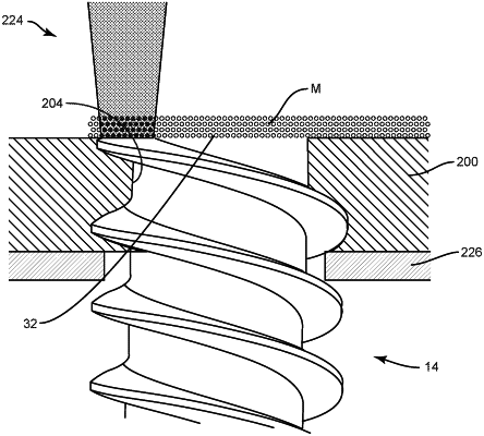
a build plate mounted with the enclosure, the build plate comprising opposite proximal and distal surfaces, the build plate defining a plurality of spaced apart openings each extending through the proximal and distal surfaces such that the openings are each in communication with the chamber, the openings each being configured for disposal of a screw shaft; and
a heating device coupled to the back wall and configured to heat a material applied to the screw shafts to fuse the material with the screw shafts,
wherein the build plate mounted with a platform of the enclosure defined by the front wall such that the build plate is movable relative to the enclosure in one or more directions, and
wherein the openings each define a female thread, the openings each including a proximal portion that extends through the proximal surface and a distal portion that extends through the distal surface, the proximal portions having a diameter that is greater than a diameter of the distal portions, the diameters of the proximal and distal portions each being greater than a major diameter of the female threads.
|