| CPC H02P 27/12 (2013.01) [H02P 21/22 (2016.02)] | 17 Claims |

|
1. A motor apparatus comprising:
a motor unit including a rotor that is rotatably disposed about an axis of rotation and a stator having an inner periphery on which a plurality of teeth parts is formed;
a switch inverter unit configured to supply electric power to the motor unit; and
a switch control unit configured to control each switch included in the switch inverter unit;
wherein the rotor is formed of a ferromagnetic material and is a switched reluctance motor,
wherein a three-phase winding of a first system and a three-phase winding of a second system are wound around the plurality of teeth parts,
wherein the switch inverter unit includes three switch groups connected in parallel, each of which having an upper switch, a middle switch, and a lower switch that are connected in series between a first potential and a second potential,
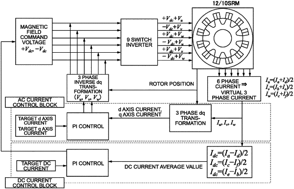
wherein the switch control unit has a vector control mode for sending a control signal to each of the first system and the second system of the switch inverter unit based on three-phase vector control,
wherein the vector control mode is configured to generate a pulsed signal by comparing signal waves and carrier waves and perform modulation control on each of the switches by way of PWM (Pulse Width Modulation),
wherein the signal waves have same phases for the first system and the second system and have amplitudes that are offset from one another, and
wherein an amount of the offset is within a range of the amplitudes of one another.
|