| CPC H02K 1/28 (2013.01) [H02K 1/276 (2013.01); H02K 15/03 (2013.01)] | 8 Claims |

|
1. A rotor of a rotary electric machine, the rotor comprising:
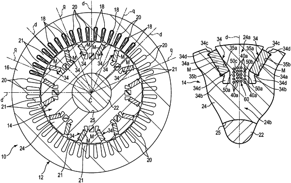
a rotor core including a plurality of magnetic poles arranged in a circumferential direction around a central axis, each of the magnetic poles including at least two magnet holding slots opposed to each other at intervals in the circumferential direction, a first core portion located between the two magnet holding slots in the circumferential direction, a second core portion located between the two magnet holding slots and the central axis, and a bridge connecting the first core portion and the second core portion; and
a plurality of permanent magnets each arranged in the magnet holding slot, wherein
when an axis passing through a center in the circumferential direction of the magnetic pole and the central axis is defined as a d-axis and an axis passing through the central axis and a boundary between magnetic poles adjacent in the circumferential direction and extending in a radial direction is defined as a q-axis, in a cross section of the rotor core orthogonal to the central axis,
the magnetic poles includes two of the magnet holding slots provided on both sides in the circumferential direction of the d-axis, and a core portion located on the q-axis and forming a magnetic path that passes magnetic flux,
the bridge includes a plurality of first center bridges located between the d-axis and the two magnet holding slots and separated from each other in the circumferential direction, and a coupling element that connects the plurality of first center bridges to each other.
|