| CPC H02J 50/10 (2016.02) [H01M 10/44 (2013.01); H02J 7/0013 (2013.01); H02J 7/0034 (2013.01); H02J 7/0042 (2013.01); H02J 7/0047 (2013.01); H02J 7/0069 (2020.01); H02J 7/00712 (2020.01)] | 25 Claims |

|
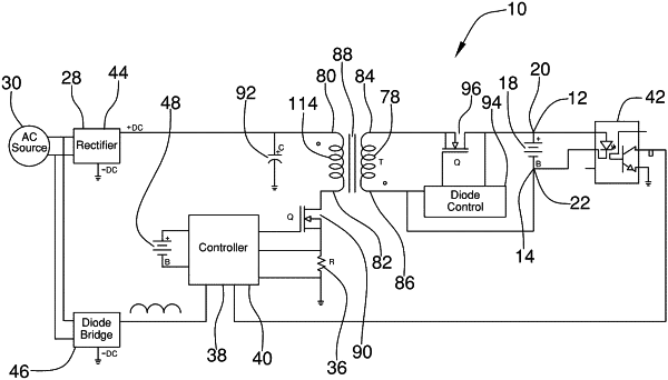
1. An impulse battery charger comprising:
a first charging contact and a second charging contact each being configured for receiving a respective charging terminal of a battery to be charged;
a first terminal and a second terminal being configured for electrically connecting to a source of direct current (SDC);
an inductor having a first end and a second end;
a switching module operationally engaged to the inductor enabling selective engagement of the inductor with the battery and selective isolation of the inductor from the SDC;
a current sensor configured to measure current flowing between the inductor, the first terminal, and second terminal; and
a controller being operationally engaged to the current sensor and the switching module for alternating the switching module between a first configuration and a second configuration in response to a signal from the current sensor indicating that the current between the inductor, the first terminal, and second terminal exceeds a predetermined threshold value, where, in the first configuration, the inductor is connected to the first terminal and the second terminal allowing the SDC to magnetically energize the inductor, and where, in the second configuration, the inductor is isolated from the SDC and is engaged to the battery enabling magnetic energy stored in the inductor to pass as direct current to the battery for charging the battery.
|
|
17. A method of charging a battery using an impulse battery charger, the method comprising steps of:
providing an impulse battery charger including
a first charging contact and a second charging contact each being configured for receiving a respective charging terminal of a battery to be charged;
a first terminal and a second terminal being configured for electrically connecting to a source of direct current (SDC);
an inductor having a first end and a second end;
a switching module operationally engaged to the inductor enabling selective engagement of the inductor with the battery and selective isolation of the inductor from the SDC;
a current sensor configured to measure current flowing between the inductor, the first terminal, and second terminal; and
a controller being operationally engaged to the current sensor and the switching module for alternating the switching module between a first configuration and a second configuration in response to a signal from the current sensor indicating that the current between the inductor, the first terminal, and second terminal exceeds a predetermined threshold value, where, in the first configuration, the inductor is connected to the first terminal and the second terminal allowing the SDC to magnetically energize the inductor, and where, in the second configuration, the inductor is isolated from the SDC and is engaged to the battery enabling magnetic energy stored in the inductor to pass as direct current to the battery for charging the battery
(a) connecting the impulse battery charger to an SDC using the first terminal and the second terminal;
(b) connecting a battery to the impulse battery charger using the first charging contact and the second charging contact;
(c) placing of the switching module by the controller into the first configuration to charge the inductor while the battery is isolated from the SDC by the switching module;
(d) measuring by the current sensor of current between the inductor, the first terminal, and the second terminal;
(e) signaling of the current sensor to the controller when a current level between the inductor, the first terminal and the second terminal exceeds a predetermined threshold;
(f) placing of the switching module by the controller into the second configuration such that the inductor discharges to the battery while the inductor is isolated from the SDC by the switching module; and
(h) returning to step (c).
|