| CPC H01R 13/6315 (2013.01) [B60R 25/0215 (2013.01); B62D 1/16 (2013.01); B62D 15/0215 (2013.01); G01B 7/30 (2013.01); G01D 5/145 (2013.01); H01R 12/712 (2013.01); H01R 2201/20 (2013.01)] | 10 Claims |

|
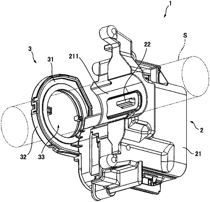
1. A sensor unit configured to be coupled to a steering shaft for use in steering a mobile entity, the sensor unit comprising:
a first circuit board including a first signal output part of a first sensor, the first signal output part being configured to output a first signal corresponding to a first operation state of a first mechanism for locking rotation of the steering shaft;
a second circuit board including a second signal output part of a second sensor, the second signal output part being configured to output a second signal corresponding to a second operation state of a second mechanism for detecting a rotation angle of the steering shaft; and
a connector electrically connecting the first circuit board and the second circuit board while allowing relative displacement therebetween.
|