| CPC H01F 27/025 (2013.01) [H01F 27/08 (2013.01); H01F 27/24 (2013.01); H01F 27/28 (2013.01); H01F 41/0206 (2013.01)] | 2 Claims |

|
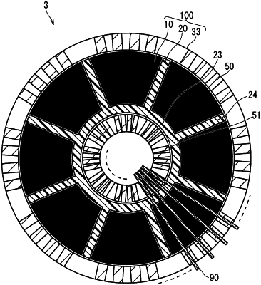
1. A reactor, comprising:
a plurality of divided cores having a shape obtained by dividing an annular core in a circumferential direction, the divided cores being made of a soft magnetic material;
a core gap part disposed between the divided cores in the annular core formed by combining the plurality of divided cores, the core gap part being made of a non-magnetic material;
an annular heat-dissipating case that houses the divided cores and the core gap part; and
a coil wound around the heat-dissipating case,
wherein,
one end surface of the heat-dissipating case is an open end surface,
the heat-dissipating case includes cutout portions on edges of an outer circumferential surface and an inner circumferential surface that are in contact with the open end surface,
the coil is wound along the cutout portions, and
the cutout portions in the heat-dissipating case are disposed distant from the core gap part so that the coil wound along the cutout portions is disposed only in a region overlapping the divided cores.
|