| CPC G05B 19/182 (2013.01) [G05B 2219/34224 (2013.01); G05B 2219/39468 (2013.01)] | 4 Claims |

|
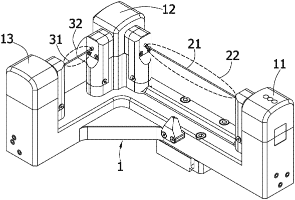
1. A tool detector which is disposed on a table of a computer numerical control (CNC) machine provided with at least one rotating shaft, three linear axes, and a control device, the tool detector comprising:
a right-angle triangular base which is provided with a first angular position, a second angular position, and a third angular position;
a main light ray emitted from a light source disposed on the first angular position to a plane mirror arranged at the second angular position so that a reflected light ray is generated due to the plane mirror and incident into a coordinate origin at a center of symmetry of a quadrant detector located at the third angular position to generate a light receiving area, wherein the quadrant detector is disposed by a diagonal method in which a coordinate axis of the quadrant detector is rotated with respect to a coordinate origin through an angle of inclination and arranged at the third angular position; and
an automatic controller in communication with the control device, the automatic controller comprising a correcting unit and a conserved common variable module, wherein a standard value set, an original value set, and a measured value set are stored in the conserved common variable module;
wherein the control device drives a standard bar to move and form a shaded area on the quadrant detector; then a reference coordinate is defined by projection of the shaded area in multi-dimensional directions in a measurement space of the main light ray while a position coordinate is defined by projection of the shaded area in multi-dimensional directions in a complex vector space of the reflected light ray wherein the shaded area, an effective cross sectional area, and an effective area in the reference coordinate or the position coordinate respectively are used to perform an error analysis on the original value set and the measured value set to get a difference of an unfinished tool, wherein the difference is transmitted to the control device by the correcting unit to reset a compensation of the unfinished tool;
wherein orthogonal projection of the reference coordinate and the position coordinate on a hypotenuse of the right-angle triangular base is also converted into a spatial coordinate which is a crossing zero and then the control device drives the standard bar to the reference coordinate and the position coordinate repeatedly at a time interval to get spatial coordinates which are used for measurement of a thermal variable of the CNC machine.
|