| CPC F23R 3/28 (2013.01) [F02C 3/06 (2013.01); F05D 2240/35 (2013.01)] | 11 Claims |

|
1. A combustor comprising:
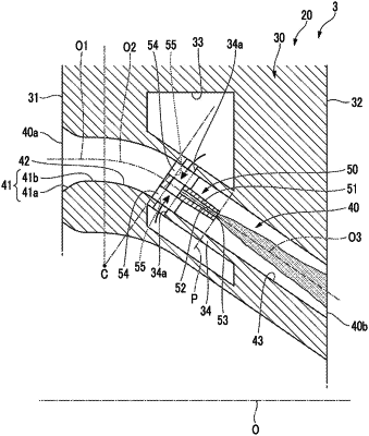
a pipe plate that has an upstream side end surface and a downstream side end surface, the upstream side end surface and the downstream side end surface extending in a direction that is transverse to a combustor axis, and in which an air hole penetrating the upstream side end surface and the downstream side end surface is formed; and
a fuel jetting portion that jets a fuel to air flowing in the air hole,
wherein the air hole has
a curved flow path that is curved toward the combustor axis as the curved flow path extends toward a downstream end of the air hole, and
an inclined flow path that is continuously connected to a downstream end of the curved flow path and that extends by being inclined with respect to the combustor axis to be open to the downstream side end surface, and
wherein a fuel jetting position where the fuel jetting portion jets the fuel is closer to the downstream end of the air hole with respect to an upstream end of the curved flow path.
|