| CPC F16H 25/2204 (2013.01) [F16H 2025/2031 (2013.01); F16H 2025/2075 (2013.01)] | 14 Claims |

|
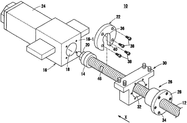
1. A linear motion device comprising:
a ball screw;
a nut configured to move with respect to the ball screw in an axial direction thereof in accordance with rotation of the ball screw;
a bearing mounted on an outer periphery of the ball screw;
a housing configured to support the ball screw through the bearing;
a nut holder configured to hold the nut therein and through which the ball screw passes; and
a restricting member that has a through hole in a center portion thereof, is disposed between the bearing and the nut holder, is fixed to the housing in a state where the ball screw is inserted into the through hole, and restricts movement of the bearing in the axial direction in the housing,
wherein the restricting member includes a cutout portion extending in a radial direction from an inner peripheral surface of the through hole to an outer peripheral surface of the restricting member, and
wherein the ball screw includes a planar portion formed by partially cutting out a part of an outer peripheral surface of the ball screw.
|