| CPC F16C 19/26 (2013.01) [F16C 33/34 (2013.01); F16C 33/366 (2013.01); F16C 33/583 (2013.01); F16C 33/585 (2013.01); F16C 19/362 (2013.01); F16C 19/364 (2013.01); F16C 2380/26 (2013.01)] | 10 Claims |

|
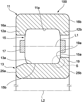
1. A roller bearing comprising:
an outer ring having a raceway surface on an inner circumferential surface thereof;
an inner ring having a raceway surface on an outer circumferential surface thereof; and
a plurality of rollers rollably disposed between the outer ring and the inner ring, wherein
on one or both of the outer ring and the inner ring, flange portions each protruding in a radial direction from the raceway surface and having a guide surface which guides each of the plurality of rollers in sliding contact with a roller end surface of each of the plurality of rollers are formed,
each of the plurality of rollers includes chamfered portions which are formed at both axial ends of a roller outer circumferential surface, and roller inclined surfaces each of which is provided to a roller inner diameter side of the roller end surface from an axial end of the chamfered portion and faces the guide surface of the flange portion, and
when in a cross section taken along a plane including a rotation axis of each of the plurality of rollers and a bearing central axis, a radial position of the roller inclined surface facing to an end portion of the guide surface on a flange portion protruding side is defined as a first position, a radial position of a boundary between the chamfered portion and the roller inclined surface is defined as a second position, an intersection angle between a tangent line of the roller inclined surface at the first position and a perpendicular line of the rotation axis of each of the plurality of rollers is defined as α, an intersection angle between a tangent line of the roller inclined surface at the second position and a perpendicular line of the rotation axis of each of the plurality of rollers is defined as β, and an intersection angle between the guide surface and a perpendicular line of the bearing central axis is defined as θ, α<θ<β is satisfied.
|