| CPC F04D 29/4233 (2013.01) [F04D 25/06 (2013.01); F04D 29/041 (2013.01); F04D 29/186 (2013.01); F04D 29/28 (2013.01)] | 14 Claims |

|
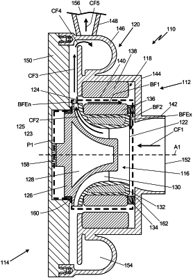
1. A shaftless rotary machine comprising:
an impeller comprising:
a center axis, wherein the impeller is configured to rotate around the center axis;
a radially outer side of the impeller, wherein the radially outer side of the impeller is an exit of the impeller;
a hub;
blades connected to the hub; and
a shroud connected to the blades;
a motor positioned radially outward from the impeller, the motor comprising:
a rotor connected to the shroud; and
a stator;
a housing having an inlet, an outlet, and a duct extending from the inlet to the outlet, wherein the duct partially surrounds the motor and the impeller; and
a bypass flow path extending between the stator and the rotor, the bypass flow path comprising an entrance and an exit, the entrance of the bypass flow path is disposed radially outward from the radially outer side of the impeller relative to the center axis, and the exit of the bypass flow path is disposed axially between the rotor and the inlet relative to the center axis, wherein the bypass flow path comprises only a single turn between the entrance of the bypass flow path and the exit of the bypass flow path, and the exit of the bypass flow path is fluidically connected to the inlet, and
wherein the shaftless rotary machine does not comprise a shaft.
|