| CPC E02F 9/2004 (2013.01) | 20 Claims |

|
1. A working machine, comprising:
a machine body;
an operator's seat provided on the machine body; and
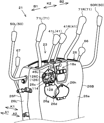
a manipulator base provided in front of the operator's seat, the manipulator base including
an operation support shaft extending in a width direction of the machine body,
an operation member supported such that the operation member is rotatable about an axis of the operation support shaft relative to the operation support shaft, and
a lock mechanism switchable between a locking state and an unlocking state, the locking state being a state in which a movement of the operation member is restricted, the unlocking state being a state in which the movement of the operation member is allowed,
the lock mechanism including
an engagement portion to rotate together with the operation member,
a lock body including an engaged portion for engagement with the engagement portion,
a lock support shaft supporting one of opposite end portions of the lock body rotatably, and
a driving portion to apply a driving force to the other of the opposite end portions of the lock body, wherein
the engaged portion is provided at an intermediate portion between the one of the opposite end portions of the lock body and the other of the opposite end portions of the lock body, and
the lock body is configured to be rotated about an axis of the lock support shaft by the driving force applied by the driving portion to change in position between an engagement position in which the engaged portion is in engagement with the engagement portion and a disengagement position in which the engaged portion is not in engagement with the engagement portion.
|