| CPC B64D 11/0641 (2014.12) | 9 Claims |

|
1. An aircraft seat, the aircraft seat comprising:
an aircraft seat frame, the aircraft seat frame including one or more seatback frames and a seat pan frame; and
a self-supporting berthing platform system, the self-supporting berthing platform system comprising:
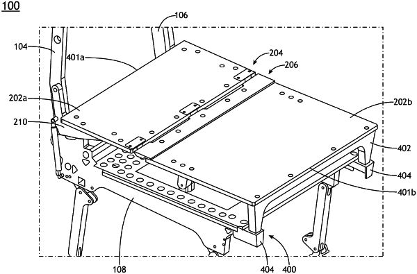
a plurality of articulated panels, the plurality of articulated panels including a first panel coupled to a second panel via at least one hinge assembly, the plurality of articulated panels configured to pivot between at least one of an upright position and a berth position via an articulated mechanism;
a hinge reinforcement assembly, the hinge reinforcement assembly including a first reinforcement member coupled to a portion of the first panel, the hinge reinforcement assembly further including a second reinforcement member coupled to a portion of the second panel, the hinge reinforcement assembly further including a flange coupled to an additional portion of the second panel, a portion of the first reinforcement member configured to overlap with a portion of the second reinforcement member;
a panel reinforcement assembly, the panel reinforcement assembly comprising:
a first panel reinforcement member coupled to a portion of the first panel and a portion of at least one of the one or more seatback frames; and
a second panel reinforcement member sub-assembly coupled to a portion of the second panel, the second panel reinforcement member sub-assembly including at least one panel leg and at least one support block;
wherein the at least one support block includes a rotatable support block configured to rotate via a rotation sub-assembly;
wherein the rotation sub-assembly comprises:
a ball plunger; and
a locking plate, the ball plunger configured to engage with one or more portions of the locking plate to secure the rotatable support block in at least one of a stowed position or a deployed position.
|