| CPC B64C 27/467 (2013.01) [B64C 27/473 (2013.01)] | 20 Claims |

|
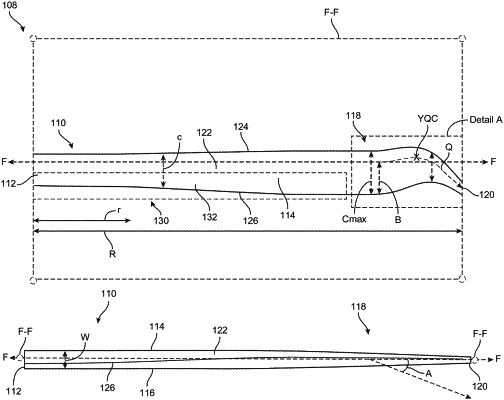
1. A rotor blade of a rotor blade assembly, the rotor blade comprising:
a blade root;
a blade tip; and
a blade body extending from the blade root to the blade tip and comprising a leading edge and a trailing edge, the blade body defining a feathering axis, wherein
the leading edge and the trailing edge each include a first portion that extends toward a first direction and a second portion that extends toward a second direction opposite the first direction,
a local twist angle of the rotor blade is approximately 9.15 degrees throughout a first zero gradient region in the range of approximately r/R=0.0 to r/R=0.2, where R is a radius of the rotor blade measured along the feathering axis from the blade root to the blade tip and r is a radial location measured from the blade root along the feathering axis, and
at a given radial location along the feathering axis in the direction that r/R is increasing, (i) a chord length extending from the leading edge to the trailing edge is decreasing in value from a first chord length, (ii) a distance between the trailing edge and the feathering axis is decreasing in value from a first distance, and (iii) the first portion of the leading edge is extending further in the first direction.
|