| CPC B23Q 3/106 (2013.01) [F15B 15/22 (2013.01); B23Q 2703/12 (2013.01)] | 7 Claims |

|
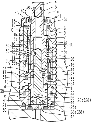
1. A work support comprising:
a support rod (3) inserted in a housing (1) so as to be movable toward a leading end side and toward a base end side in an axial direction of the support rod (3);
a collet (5) fitted over an outer peripheral wall of the support rod (3);
a piston (6) inserted in the housing (1) so as to be movable in the axial direction, the piston (6) being configured to cause the collet (5) to grip and hold the support rod (3);
an actuation chamber (21) provided in a base end portion of the housing (1);
an output member (24) configured to be moved toward the leading end side in the axial direction by pressurized oil supplied to the actuation chamber (21);
a release spring (33) attached in the actuation chamber (21), to which the pressurized oil is supplied, and between a leading end wall (31) of the actuation chamber (21) and a flange portion (25a) provided to a base end portion of the output member (24), the release spring (33) being configured to bias the output member (24) toward the base end side; and
a biasing mechanism (38, 41) configured to bias the support rod (3) and the output member (24) so that the support rod (3) and the output member (24) recede from each other;
wherein the actuation chamber (21) includes a base-end-side actuation chamber (43) provided on the base end side in the axial direction relative to the flange portion (25a), and a leading-end-side actuation chamber (44) provided on the leading end side in the axial direction relative to the flange portion (25a), the leading-end-side actuation chamber (44) being communicatively connected to the base-end-side actuation chamber (43), wherein the release spring (33) is disposed in the leading-end-side actuation chamber (44).
|