| CPC B23Q 17/249 (2013.01) [B23Q 15/14 (2013.01); B23Q 15/22 (2013.01); B23Q 17/22 (2013.01); B23Q 17/24 (2013.01); B23Q 17/2414 (2013.01); B23Q 17/2428 (2013.01); G05B 19/291 (2013.01); G06T 7/0004 (2013.01); G06T 7/75 (2017.01); G06T 2207/30164 (2013.01)] | 6 Claims |

|
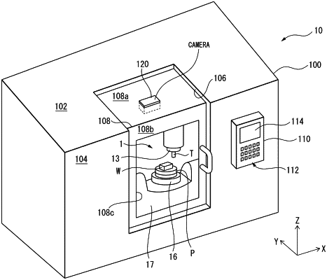
1. A machine tool on-machine measurement method for determining a position of a workpiece or jig on a table with an imaging device by changing the posture of the table with a rotary feed axis, wherein the table is enclosed within a cover and the imaging device is arranged on the cover, the method comprising:
an upward imaging step in which the rotary feed axis is rotated to move the table to a first imaging position so as to orient an upper surface of the table perpendicular to a line-of-sight direction of the imaging device and the workpiece or jig is imaged with the imaging device,
a side imaging step in which the rotary feed axis is rotated to move the table to a second imaging position so as to orient the upper surface of the table parallel to the line-of-sight direction of the imaging device and the workpiece or jig is imaged with the imaging device, and
a calculation step in which the position and a height of the workpiece or jig are calculated by a controller of the machine tool from the images captured in the upward imaging step and the side imaging step
wherein the calculation step further comprises the steps of:
extracting image edge pixels from the images,
measuring the position of the workpiece or the jig by counting the number of pixels of the image captured in the upward imaging step, and
measuring the height of the workpiece or the jig in the direction perpendicular to the upper surface of the table by counting the number of the pixels of the image captured in the side imaging step.
|