| CPC B23P 19/045 (2013.01) [B25B 27/24 (2013.01); B25J 15/0095 (2013.01); B25J 15/0038 (2013.01); F01L 3/10 (2013.01)] | 5 Claims |

|
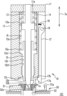
1. A retainer gripping device configured to grip a retainer accommodating a set of cotters inside the retainer, the retainer gripping device comprising:
a retainer gripping unit configured to grip the retainer;
a retainer supporting portion configured such that the retainer gripped by the retainer gripping unit is placed in a state in which the set of cotters are accommodated inside the retainer; and
a cotter supporting portion configured to support lower end edge portions of the cotters accommodated inside the retainer in a state in which the lower end edge portions are lifted upward higher than a lower end edge portion of the retainer, wherein the retainer gripping unit includes a plunging pin member inserted from above between the set of cotters supported by the cotter supporting portion, and the plunging pin member includes a tapered portion on a distal end portion of the plunging pin member, the tapered portion being reduced in diameter toward a distal end side of the plunging pin member.
|