| CPC B64G 5/00 (2013.01) | 4 Claims |

|
1. A Z-shaped layout fixed-length double-rope grouped closed force system capturing and recycling net system configured to capture a rocket case body, comprising:
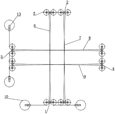
a capturing and intercepting assembly, wherein the capturing and intercepting assembly comprises a rope group a (1), a rope group b (2), a rope group c (3), and a rope group d (4), the rope group a (1), the rope group b (2), the rope group c (3) and the rope group d (4) are each wound with two movable wheel groups (5) oppositely arranged, the rope group a (1) between the movable wheel groups (5) is an intercepting section a (6), the rope group b (2) between the two movable wheel groups (5) is an intercepting section b (7), the rope group c (3) between the two movable wheel groups (5) is an intercepting section c (8), the rope group d (4) between the two movable wheel groups (5) is an intercepting section d (9), the intercepting section a (6) and the intercepting section b (7) are arranged in parallel, the intercepting section c (8) and the intercepting section d (9) are arranged in parallel, and the intercepting section a (6) and the intercepting section c (8) are arranged perpendicularly; and
a supporting assembly, wherein the supporting assembly comprises four stand columns (10) fixedly connected to a base (11), a guide rail (12) is fixedly connected between each two adjacent stand columns (10), the movable wheel groups (5) are slidingly connected to the guide rails (12), traction devices (15) are drivingly connected to the movable wheel groups (5), a plurality of fixed wheels (13) are arranged on the stand column (10), the rope group a (1), the rope group b (2), the rope group c (3) and the rope group d (4) are each wound around the different fixed wheels (13), ends of the rope group a (1), the rope group b (2), the rope group c (3) and the rope group d (4) are each connected to the four stand columns (10).
|