| CPC H03K 17/082 (2013.01) [H03K 2217/0027 (2013.01)] | 10 Claims |

|
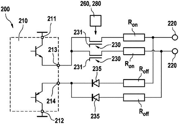
1. A circuit arrangement (200, 200′) for controlling a plurality of semiconductor switches (120) connected in parallel, the circuit arrangement comprising:
a switch-on terminal (213),
a switch-off terminal (214),
a plurality of control terminals (220), which are each provided for connection to a control terminal (123) of one of the plurality of semiconductor switches (120),
wherein the switch-on terminal (213) and the switch-off terminal (214) are each connected to each of the plurality of control terminals (220), and wherein a potential of the switch-on terminal (213) is switchable, and
wherein a switch disconnector (230) is provided between the switch-on terminal (213) and at least one of the control terminals (220),
further comprising
at least one detection and control arrangement (260, 280), which is designed to detect a current flow into the at least one of the control terminals (220) and, when a short circuit is identified from the current flow exceeding a preset threshold value for at least a preset time period, to control the switch disconnector (230) causing it to open, and
a diode (235) provided between the switch-off terminal (214) and the at least one of the control terminals (220), the diode (235) having its forward direction in the direction of the switch-off terminal (214), and the diode connected to the switch-off terminal (214) and a switch-off resistor, the switch-off resistor provided between the switch-off terminal (214) and the at least one of the control terminals (220).
|