| CPC H03B 5/24 (2013.01) | 13 Claims |

|
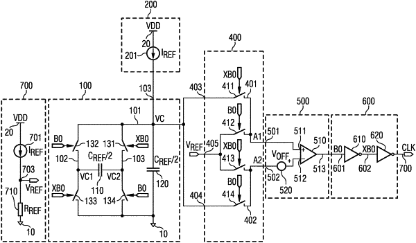
1. An oscillator circuit arrangement, comprising:
a switched capacitor circuit having at least one output terminal, a supply terminal and a terminal for ground potential, comprising at least one capacitor having at least one terminal, the switched capacitor circuit configured to selectively couple the at least one terminal to one of the supply terminal and the terminal for ground potential, the output terminal coupled to the at least one capacitor;
a chopper circuit having a first input terminal and a second input terminal connected to the switched capacitor circuit, a terminal for a reference potential, a first output terminal and a second output terminal, the chopper circuit configured to selectively couple the first output terminal to one of the first input terminal and the terminal for a reference potential and to couple the second output terminal to one of the second input terminal and the terminal for a reference potential;
a comparator circuit having input terminals connected to the output terminals of the chopper circuit and an output terminal;
a buffer circuit including at least one buffer connected to the output terminal of the comparator circuit, to the switched capacitor circuit to control selective coupling of the at least one capacitor and to the chopper circuit (400) to control selective coupling of the first and second output terminals; and
an output terminal connected to the buffer circuit to supply a clock signal,
wherein the switched capacitor circuit comprises a fifth, a sixth, a seventh and an eighth switch, wherein the at least one terminal of the at least one capacitor is connected to the output terminal of the switched capacitor circuit through the sixth switch and to the terminal for ground potential through the seventh switch, wherein another terminal of the at least one capacitor is connected to the output terminal of the switched capacitor circuit through the fifth switch and to the terminal for ground potential through the eighth switch, wherein the fifth and seventh switches are operated in phase with each other and the sixth and eighth switches are operated out of phase or complementary with the fifth and seventh switches.
|