| CPC H02P 27/06 (2013.01) [H02J 7/0063 (2013.01); H02J 7/342 (2020.01); H02J 7/345 (2013.01); H02P 3/18 (2013.01); H02P 23/14 (2013.01); H02J 2207/50 (2020.01)] | 10 Claims |

|
1. A motor drive system for driving a motor, and the motor drive system comprising:
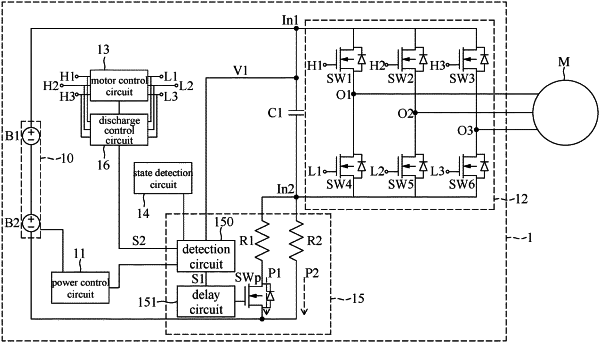
a battery pack including a first battery unit and a second battery unit connected in series between a first input terminal and a second input terminal;
a power control circuit configured to control the battery pack to be turned on and off;
a capacitor connected between the first input terminal and the second input terminal;
an inverter circuit connected to the first input terminal and the second input terminal to be powered by the battery pack, wherein the inverter circuit has a plurality of switch elements that are connected to form a plurality of output terminals, and the plurality of output terminals are connected to a plurality of phase windings of the motor, respectively;
a motor control circuit configured to generate a set of motor control signals, so as to control the plurality of switch elements to be turned on and off, such that each of the phase windings of the motor is energized to drive the motor;
a state detection circuit configured to detect an operating state of the motor drive system;
a precharge circuit, including:
a high-impedance path connected between the second input terminal and the battery pack;
a low-impedance path connected between the second input terminal and the battery pack, wherein a resistance of the high-impedance path is greater than a resistance of the low-impedance path;
a precharge switch disposed on the low-impedance path;
a detection circuit configured to:
compare a first voltage at the first input terminal with a precharge start-up voltage to correspondingly generate a detection result signal, wherein, in response to the first voltage being higher than the precharge start-up voltage, the detection result signal is used to control the precharge switch to be turned on, and in response to the first voltage being less than or equal to the precharge start-up voltage, the detection result signal is used to control the precharge switch to be turned off; and
detect whether or not the operating state is a non-driving mode and whether or not the first voltage decreases with time, and in response to detecting that the operating state is the non-driving mode and the first voltage decreases with time, output a discharge indication signal for performing a discharge process on the capacitor, and stop outputting the discharge indication signal in response to detecting that the first voltage no longer decreases with time; and
a delay circuit disposed between the detection circuit and the precharge switch, wherein the delay circuit is configured to delay the detection result signal for a predetermined delay time; and
a discharge control circuit configured to execute the discharge process according to the discharge indication signal, including:
obtaining a current operating angle of the motor through the motor control circuit; and
correcting, according to the current operation angle, the set of the motor control signals by a correction angle, so as to stop the motor and enter a discharge mode.
|