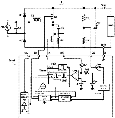
| CPC H02M 1/4233 (2013.01) [H02M 1/0058 (2021.05); H02M 1/0085 (2021.05)] | 7 Claims |

|
1. An integrated circuit that performs synchronous rectification control of a bridgeless power factor correction circuit in a critical mode comprising:
a bridgeless power factor correction circuit of a critical mode comprising:
a first diode;
a second diode electrically connected in series with the first diode;
an output smoothing capacitor electrically connected to the first diode and the second diode;
an AC power supply that includes a first terminal and a second terminal and is electrically connected to the first diode and the second diode;
a first reactor that includes a first terminal and a second terminal and is connected to the second terminal of the AC power supply;
a half-bridge circuit including a first NMOSFET and a second NMOSFET, the second terminal of the first reactor electrically connected to a connection point between the first NMOSFET and the second NMOSFET; and
a differentiation circuit that comprises a capacitor and a resistor and is connected between main electrodes of the second NMOSFET in the half-bridge circuit; wherein
the integrated circuit detects an output voltage of the output smoothing capacitor, compares the output voltage with a reference voltage, and controls the half-bridge circuit to be on and off based on an error signal between the output voltage and the reference voltage, and
a next ON time of a synchronous rectification switch operation of the half-bridge circuit is assigned based on a time that is obtained by subtracting a predetermined time from a measured time comprising a period between OFF timing of an active switch of the half-bridge circuit and timing of an output of a differentiation signal generated by the differentiation circuit.
|