| CPC H02K 7/003 (2013.01) [H02K 7/145 (2013.01); H02K 9/06 (2013.01)] | 16 Claims |

|
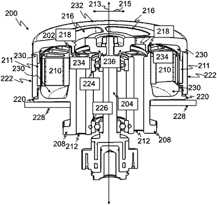
1. An electric motor comprising:
a stator assembly; and
a rotor comprising a rotor shaft assembly rotatably mounted inside the stator assembly;
wherein said rotor shaft assembly comprising:
i. at least one section that is configured to extend in an axial direction of the rotor shaft assembly outside of the stator assembly of the electric motor, when the rotor shaft assembly is rotatably mounted inside the stator assembly, and
ii. an electrical insulator connected to the at least one section and the electrical insulator is configured to connect to an output shaft for connecting with a tool and/or accessory, or configured to connect directly to a tool and/or accessory to be driven by the electric motor; and
wherein said stator assembly comprises a stator hub comprising electromagnets, and the stator hub comprises cooling channels extending in a direction that is parallel to a longitudinal direction of the rotor shaft assembly and the cooling channels are positioned between the rotor shaft assembly and the electromagnets.
|