| CPC H01J 37/32715 (2013.01) [C23C 16/0227 (2013.01); C23C 16/4583 (2013.01); C23C 16/50 (2013.01); H01J 37/32743 (2013.01); H01J 37/32899 (2013.01); H01L 21/67028 (2013.01); H01L 21/67034 (2013.01); H01L 21/6704 (2013.01); H01L 21/67196 (2013.01); H01L 21/67706 (2013.01); H01J 2237/2007 (2013.01); H01J 2237/20214 (2013.01); H01J 2237/3321 (2013.01)] | 8 Claims |

|
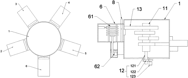
1. A plasma enhanced chemical vapor deposition (PECVD) apparatus, comprising: a substrate tray, a transfer chamber, a load lock, a cleaning chamber, a spin-drying chamber, a deposition chamber, and an unload lock;
wherein the load lock, the cleaning chamber, the spin-drying chamber, the deposition chamber, and the unload lock are successively spirally arranged on a side wall of the transfer chamber;
a spiral conveyor device is arranged in the transfer chamber, wherein the spiral conveyor device comprises a conveyor rod, a spiral drive mechanism, and a plurality of conveyor assemblies;
wherein the conveyor rod is vertically arranged in the transfer chamber, and the plurality of conveyor assemblies are spirally arranged on the conveyor rod, and
wherein the spiral drive mechanism is configured to drive the conveyor rod to undergo a spiral ascending or descending movement; and
a spin-drying device is arranged in the spin-drying chamber, wherein the drying device comprises a drying support, and a support base, a lift mechanism, a plurality of clamp fingers, a connection rod, a rotation mechanism, and a jack mechanism;
wherein the support base is in lift connection to the spin-drying support, and is driven to ascend or descend by the lift mechanism to receive the substrate tray fed by the conveyor assemblies,
wherein the plurality of clamp fingers are circumferentially arrayed on an outer side of the support base, and are hinged to the spin-drying support, wherein a bottom of the support base is hinged to one end of the each of the clamp fingers via the connection rod,
wherein the rotation mechanism is arranged at a bottom of the spin-drying support, and is configured to drive the drying support to reciprocally rotate,
wherein the jack mechanism is arranged on the spin-drying support, and is configured to jack to separate a substrate on the substrate tray, and
wherein the jack mechanism comprises a plurality of jack assemblies, each of the jack assemblies comprising a jack rod, a jack elastic member, and a press plate, wherein the press plate is secured to a bottom of the jack rod, two ends of the jack elastic member are respectively securely connected to the spin-drying support and the press plate, and the support plate and the spin-drying support are both provided with a jack groove slidably engageable with the jack rod.
|