| CPC H01H 50/60 (2013.01) [H01H 45/12 (2013.01); H01H 50/14 (2013.01); H01H 50/58 (2013.01)] | 13 Claims |

|
1. An electromagnetic relay, comprising:
a housing;
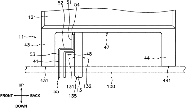
a first fixed terminal extending from inside the housing to outside the housing, with the portion of the first fixed terminal lying outside the housing having a pair of major surfaces on opposite sides thereof and side surfaces disposed between the two major surfaces;
a movable contact piece disposed in the housing, the movable contact piece facing the first fixed terminal;
a drive device configured to move the movable contact piece in a contact direction and an opening direction, the contact direction being a direction in which the movable contact piece contacts the first fixed terminal, the opening direction being a direction in which the movable contact piece is separate from the first fixed terminal; and
a first heat dissipation member disposed outside the housing, the first heat dissipation member being provided as a separate component from the first fixed terminal, the first heat dissipation member being attached to one of the major surfaces of the portion of the first fixed terminal lying outside the housing in heat-transferring relationship therewith, the first heat dissipation member including a terminal portion that is 1) spaced apart from said one of the major surfaces of the portion of the first fixed terminal lying outside the housing and that 2) extends in the same direction as the first fixed terminal.
|