| CPC H01H 33/66207 (2013.01) [H02B 1/36 (2013.01); H01H 2033/6665 (2013.01)] | 20 Claims |

|
1. An integrated assembly comprising:
a switchgear apparatus configured for operation at voltages up to 72.5 kV;
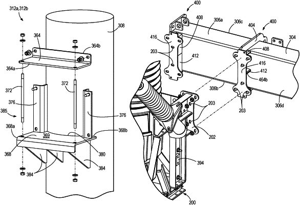
a mount assembly configured for coupling to a pole and to support the switchgear apparatus from the pole, the mount assembly including
a crossbar,
a pole mount configured for coupling to the pole and to be secured to the crossbar at different positions along a length of the crossbar,
a mounting bracket configured to support the switchgear apparatus on the crossbar, and
a pair of crossbar mounts configured to be secured to the mounting bracket for supporting the mounting bracket on the crossbar at different positions along the length of the crossbar, wherein each crossbar mount of the pair of crossbar mounts comprises a first arm having a length extending in a plane, a second arm spaced apart from the first arm and having a length extending in the plane and parallel to the first arm, a third arm extending between and coupled to a distal end of each of the first and second arms, and a flange extending between and coupled to a proximal end of each of the first and second arms, the flange configured for coupling to the mounting bracket, and the flange extending parallel to the third arm, wherein the first, second, and third arms and the flange are positioned to form an enclosed space to receive the crossbar.
|