| CPC H01G 9/15 (2013.01) [H01G 9/052 (2013.01); H01G 9/10 (2013.01)] | 14 Claims |

|
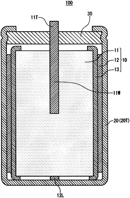
1. An electrolytic capacitor comprising:
a capacitor element;
a liquid component;
a case housing the capacitor element and the liquid component; and
a sealing member sealing the case, wherein:
the capacitor element includes:
a porous sintered body including a dielectric layer, the porous sintered body having a top surface, a bottom surface and an outer peripheral surface between the top surface and the bottom surface;
a cathode foil facing the outer peripheral surface of the porous sintered body;
a separator disposed between the cathode foil and the porous sintered body, the separator covering the outer peripheral surface of the porous sintered body; and
a conductive polymer disposed in an inside of the porous sintered body and in the separator, the conductive polymer covering at least a part of a surface of the dielectric layer,
the conductive polymer forms, in the separator, a conductive path electrically connecting the cathode foil and the dielectric layer disposed in the inside of the porous sintered body, and
the capacitor element is impregnated with the liquid component.
|