| CPC H01F 5/06 (2013.01) [H01F 5/02 (2013.01); H01F 27/325 (2013.01); H01F 7/16 (2013.01)] | 4 Claims |

|
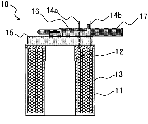
1. A solenoid coil, comprising:
a coil having a first end surface and a second end surface on its both ends in an axial direction;
a member which is in contact with the first end surface, and has a groove through which the wire material of the coil passes;
an insulating resin formed to coat at least an outer circumferential surface and the second end surface of the coil, wherein the resin with a substantially U-shaped section is continuously coated on at least a part of an inner circumferential surface of the coil via an area from the outer circumferential surface to the second end surface; and
a cylindrical bobbin disposed at an inner side of the coil, wherein
the bobbin is provided with the member in the form of a flange at a side of the first end surface, and
at least a part of the wire material is wound around an outer circumference of the bobbin, and
the resin is coated on the inner circumferential surface of the coil at a part where the wire material is not wound around the outer circumference of the bobbin.
|