| CPC G09G 5/10 (2013.01) [G03H 2001/0088 (2013.01); G03H 2001/0216 (2013.01); G09G 2320/0646 (2013.01)] | 2 Claims |

|
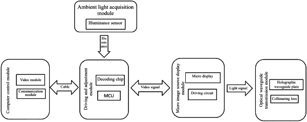
1. An adaptive adjustment method for a brightness of a holographic waveguide display device, wherein an adjustment system adopted by the adaptive adjustment method comprises a computer control module, a driving and adjustment module, a micro image source display module, an optical waveguide transmission module and an ambient light acquisition module, wherein the computer control module is used for providing a control signal and a video signal to a micro image source; the driving and adjustment module is used for illuminating the micro image source and changing display parameters of the micro image source; the micro image source display module is used for generating light information and transmitting the light information to the optical waveguide transmission module; the optical waveguide transmission module is used for transmitting light of the micro image source to realize augmented reality (AR) display; the ambient light acquisition module is used for acquiring illuminance information of ambient light and feeding the illuminance information back to the driving and adjustment module in real time to allow the driving and adjustment module to adjust brightness of the micro image source display module according to the illuminance information; the driving and adjustment module comprises a decoding chip and a micro control unit; the micro image source display module comprises a micro display and a driving circuit; the optical waveguide transmission module comprises a holographic waveguide plate and a collimating lens; the holographic waveguide plate comprises an in-coupling grating, a glass substrate and an out-coupling grating; the ambient light acquisition module is an illuminance sensor; the adaptive adjustment method comprises the following steps:
S1: determining overall specifications and feature parameters of the holographic waveguide display device;
S2: determining a type of each module of the adaptive adjustment system according to the overall specifications and the feature parameters;
S3: after the type of each module is determined, connecting the computer control module, the driving and adjustment module and the micro image source display module by a hardware circuit, and then writing software drive codes into the micro control unit to preliminarily illuminate the micro image source display module;
S4: combining the micro image source display module which has been illuminated in S3 and the optical waveguide transmission module to allow light of the micro image source display module to pass through the optical waveguide transmission module to reach human eyes to realized AR display;
S5: embedding the ambient light acquisition module in the holographic waveguide display device constructed in S1-S4; establishing communication between the ambient light acquisition module and the micro control unit in the driving and adjustment module to transmit the illuminance information, and transmitting, by the micro control unit, the illuminance information to the computer control module to display the illuminance information; finally, comparing the illuminance information with a result obtained by a standard illuminometer to correct illuminance data of the ambient light acquisition module;
S6: carrying out a visual perception-based subjective experiment to obtain a relationship between display brightness and environmental illuminance; and
S7: saving the relationship between the display brightness and the environmental illuminance in the micro control unit, and performing fine adjustment using a coefficient;
wherein S6 comprises the following sub-steps:
S6.1: establishing the relationship between the display brightness L and the environmental illuminance E:
L=K′lnE+L0 (2)
wherein, K′ is a constant, and Le indicates the display brightness when the environmental illuminance is 0;
S6.2: carrying out the visual perception-based subjective experiment, setting an illuminance change gradient, allowing a subject to adjust display brightness of the holographic waveguide display device under each illuminance, then selecting a minimum brightness, an appropriate brightness and a maximum brightness, and recording data; and
S6.3: designing environmental illuminance gradient segments, and recording the minimum brightness, the appropriate brightness and the maximum brightness at percentile 50 under each illuminance environment; with the environmental illuminance as an independent variable and the minimum brightness, the appropriate brightness and the maximum brightness as dependent variables, fitting three display brightness-environmental illuminance curve equations, wherein the three display brightness-environmental illuminance curve equations are a minimum brightness curve equation F1, an appropriate brightness curve equation F2 and a maximum brightness curve equation F3 respectively;
wherein saving the relationship between the display brightness and the environmental illuminance in the micro control unit in S7 comprises: saving F1, F2 and F3 in the micro control unit, and introducing a weighted mean with an adjustable coefficient; and during initialization, setting a weight coefficient α of the minimum brightness curve equation F1 and a weight coefficient c of the maximum brightness curve equation F3 to 0, and setting a weight coefficient b of the appropriate brightness curve equation F2 as 1, thus obtaining a final brightness F:
F=aF1+bF2+cF3.
|