| CPC G06F 3/0412 (2013.01) [G06F 2203/04103 (2013.01); G09G 3/3233 (2013.01); G09G 2300/0426 (2013.01); G09G 2300/0819 (2013.01); G09G 2300/0842 (2013.01); G09G 2300/0861 (2013.01)] | 18 Claims |

|
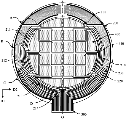
1. A touch panel, comprising a touch region and a bonding region located on a side of the touch region in a first direction, wherein the bonding region comprises:
a chip region, comprising a first edge, a second edge, a third edge, and a fourth edge, wherein the first edge and the second edge extend along a second direction, the second edge is located on a side of the first edge away from the touch region, and the third edge and the fourth edge extend along the first direction, and the first direction intersects with the second direction;
a plurality of pins located in the chip region and comprising a plurality of display pins and a plurality of touch pins, wherein the plurality of display pins are arranged along the first edge and the second edge, the plurality of touch pins are arranged along the third edge and the fourth edge, and the plurality of display pins are configured to be connected with display signal lines;
a plurality of touch electrodes located in the touch region; and
a plurality of touch signal lines, located in the touch region and the bonding region, wherein the plurality of touch signal lines are correspondingly connected with the plurality of touch electrodes and the plurality of touch pins;
wherein the chip region comprises a first pin region, a second pin region, a third pin region, a fourth pin region, a fifth pin region, and a sixth pin region, the first pin region is arranged along the first edge of the chip region, the second pin region is arranged along the second edge of the chip region, the third pin region and the fifth pin region are sequentially arranged along the third edge of the chip region, and the fourth pin region and the sixth pin region are sequentially arranged along the fourth edge of the chip region; and
wherein the plurality of touch pins comprise a plurality of touch signal output pins and a plurality of touch signal input pins, the plurality of touch signal output pins are arranged in the third pin region and the fourth pin region, and the plurality of touch signal input pins are arranged in the fifth pin region and the sixth pin region; and the touch signal output pins are configured to be connected with the touch signal lines, the touch signal input pins are configured to be connected with touch input lines, and touch signals are output to the touch signal output pins through the touch input lines and the touch signal input pins.
|