| CPC G05D 23/022 (2013.01) [F16K 11/04 (2013.01); F16K 31/002 (2013.01); G05D 23/1333 (2013.01)] | 2 Claims |

|
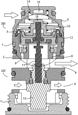
1. A water flow rate automatic control module, comprising a base, a valve body, a thermosensitive assembly and a diaphragm;
wherein the base is hermetically connected with a first end arranged at a bottom of the valve body, a cold water cavity is enclosed between the base and the valve body, and a side wall of the valve body is provided with a cold water passing hole communicated with the cold water cavity; a second end arranged at a top of the valve body is hermetically connected with an end cover, a warm water cavity is enclosed between the end cover and the valve body, and a supporting tube coaxially and fixedly connected with the valve body is arranged in the warm water cavity; and the side wall is between the two ends of the valve and is also provided with a warm water inlet hole and a warm water outlet hole, the warm water outlet hole is located above the cold water passing hole, the warm water outlet hole is located below the warm water inlet hole, a side water passage communicated with the warm water inlet hole and the warm water outlet hole is arranged between an inner wall of the valve body and the supporting tube;
the thermosensitive assembly is detachably and hermetically connected with the valve body; the thermosensitive assembly comprises a temperature sensing part and a moving rod inserted into the temperature sensing part, the temperature sensing part is arranged in the cold water cavity, and a free end of the moving rod is fixedly connected with a diaphragm support; the diaphragm support is arranged in the warm water cavity and is arranged above the supporting tube, a buckle cover is detachably connected to the diaphragm support, and the diaphragm is arranged between the diaphragm support and the buckle cover; and a return spring enabling the diaphragm to be in contact with a top of the supporting tube is arranged between the buckle cover and the end cover.
|