| CPC G03G 21/105 (2013.01) [G03G 15/0844 (2013.01); G03G 15/0858 (2013.01); G03G 15/0877 (2013.01); G03G 15/0886 (2013.01); G03G 15/0891 (2013.01); G03G 15/0896 (2013.01); G03G 21/10 (2013.01); G03G 21/12 (2013.01); G03G 21/1647 (2013.01); G03G 2215/0802 (2013.01); G03G 2221/0005 (2013.01)] | 20 Claims |

|
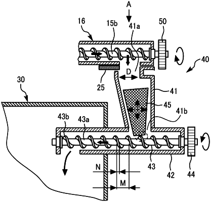
1. A powder conveying device, comprising:
a drop conveyance passage in which powder entering from an inflow port thereof is to drop;
an intersecting conveyance passage communicating with a lower end of the drop conveyance passage and extending in an intersecting direction that intersects the drop conveyance passage;
a conveying screw disposed in the intersecting conveyance passage, the conveying screw configured to rotate in a specified direction to convey the powder in the intersecting direction; and
a float movably installed in the drop conveyance passage, the float to float in the drop conveyance passage to move by contact with the conveying screw,
wherein the inflow port and the float are configured to interfere with each other to prevent the float from coming out of the inflow port of the drop conveyance passage,
wherein an opening area of the inflow port is smaller than a projected area of the float when viewed from the inflow port.
|