| CPC G01N 15/082 (2013.01) [G01N 15/0806 (2013.01); G01N 15/0826 (2013.01)] | 4 Claims |

|
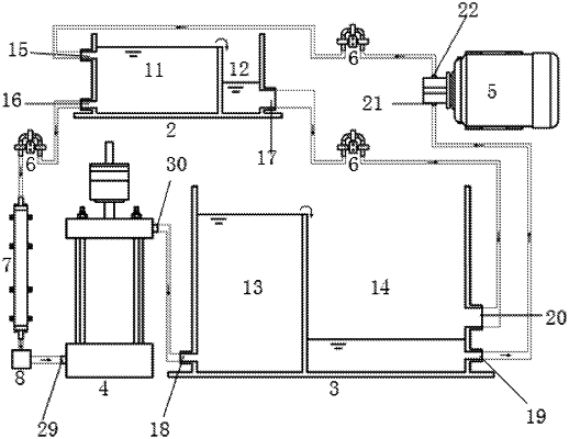
1. A seepage and internal erosion test apparatus for geotechnical centrifuges, comprising a mounting base, a lifting table fixed on the mounting base, a downstream water sink, a plurality of permeameters, a centrifugal pump, and an upstream water sink fixedly mounted on the lifting table;
wherein the upstream water sink comprises an upstream pressure stabilizing bowl and an upstream overflow bowl separated by a partition board, wherein an upstream inlet and an upstream outlet are respectively arranged at an upper portion and a lower portion of a sidewall of the upstream pressure stabilizing bowl, and an upstream overflow port is set at the lower portion of a sidewall of the upstream overflow bowl;
wherein the downstream water sink comprises a downstream pressure stabilizing bowl and a downstream overflow bowl separated by a partition board, wherein a downstream inlet is arranged at the lower portion of a sidewall of the downstream pressure stabilizing bowl, a downstream pumping port and a downstream overflow port are arranged at the lower portion of a sidewall of the downstream overflow bowl, and the downstream overflow port is higher than the downstream pumping port;
wherein the permeameter comprises a barrel, a top cap, a base pedestal, a weight table, a piston bar, an upper perforated plate, a metal net, and a lower perforated plate;
wherein the weight table comprises a disc-shaped supporting plate, a weight bar penetrating and vertically fixed in a center of the disc-shaped supporting plate, and weights with a central hole, while the weights are sleeved on the weight bar; the top cap is fixed on an upper part of the barrel, a center of the top cap is provided with a through-hole, and the piston bar passes through the through-hole; a top end of the piston bar is connected with a bottom end of the weight bar, and the bottom end of the piston bar is fixedly connected with a center of the upper perforated plate; the upper perforated plate is located in the barrel, and a diameter of the upper perforated plate is matched with an inner diameter of the barrel;
wherein a sidewall of the top cap is provided with a permeameter water outlet; the base pedestal is fixed at a lower part of the barrel, an upper surface of the base pedestal is funnel-shaped, and a metal mesh and the lower perforated plate are sequentially arranged at an opening of a funnel, diameters of the metal mesh and the lower perforated plate are matched with the inner diameter of the barrel, and the metal mesh is positioned above the lower perforated plate;
wherein a sidewall of the base pedestal is provided with a permeameter inlet;
wherein a plurality of pressure taps are arranged at intervals vertically on a sidewall of the barrel, and pore pressure gauges are installed in the pressure taps;
wherein the downstream water sink, the plurality of permeameters, the centrifugal pump and the upstream water sink are connected by pipes:
wherein a centrifugal pump water outlet is connected to the upstream inlet, the upstream outlet is connected to a permeameter water inlet, and the permeameter water outlet is connected to the downstream inlet; the downstream pumping port is connected to a centrifugal pump inlet, and the upstream overflow port is connected to the downstream overflow port;
wherein the plurality of permeameters are connected in parallel, and each branch on which the permeameters are installed is respectively provided with an electric ball valve; a temperature control module and flow meters are arranged in the pipe where the upstream outlet is connected to the permeameter inlet; and
wherein the temperature control module comprises a heat exchanger and heat exchanger adapters connected to both ends of the heat exchanger, and a pipe wall of the heat exchanger is provided with thermoelectric coolers and heat exchange fins.
|