| CPC G01M 11/335 (2013.01) [H04B 10/0775 (2013.01)] | 21 Claims |

|
1. A system for inspecting an optical transmission path constituted of a plurality of optical fibers, comprising:
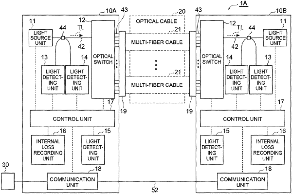
a first inspecting device configured to be provided on one end side of the optical transmission path;
a second inspecting device configured to be provided on another end side of the optical transmission path; and
a loss calculating unit configured to calculate a loss of each of the plurality of optical fibers,
wherein each of the first and second inspecting devices has
a light source unit outputting test light,
a plurality of light input/output ports each detachably connected to each of the plurality of optical fibers,
an optical switch selectively coupling the light source unit with each of the light input/output ports,
a first light detecting unit detecting a first intensity of the test light input from the first or second inspecting device on a counterpart side and passing through the optical switch,
a second light detecting unit detecting a second intensity of the test light directed from the light source unit toward the optical switch,
a third light detecting unit optically coupled to another end of a test optical fiber having one end connected to each of the plurality of light input/output ports in place of each of the plurality of optical fibers, and detecting a third intensity of the test light received from the light source unit via the test optical fiber, and
an internal loss recording unit recording a loss of an optical path inside the device obtained on a basis of a difference between the third intensity and the second intensity,
wherein the loss calculating unit calculates a loss of each of the plurality of optical fibers on a basis of a value obtained by subtracting the first intensity of the second inspecting device, a loss recorded in the internal loss recording unit of the first inspecting device, and a loss recorded in the internal loss recording unit of the second inspecting device from the second intensity of the first inspecting device, and
wherein each of the first and second inspecting devices further has a communication unit for communicating independently from the optical transmission path between the first inspecting device and the second inspecting device.
|