US 12,111,158 B2
MEMS gyroscope control circuit
Deyou Fang, Frisco, TX (US); Chao-Ming Tsai, Southlake, TX (US); Milad Alwardi, Allen, TX (US); Yamu Hu, Allen, TX (US); and David McClure, Carrollton, TX (US)
Assigned to STMicroelectronics, Inc., Coppell, TX (US)
Filed by STMicroelectronics, Inc., Coppell, TX (US)
Filed on Apr. 18, 2023, as Appl. No. 18/136,088.
Application 18/136,088 is a continuation of application No. 17/504,994, filed on Oct. 19, 2021, granted, now 11,662,205.
Application 17/504,994 is a continuation of application No. 16/452,850, filed on Jun. 26, 2019, granted, now 11,175,138, issued on Nov. 16, 2021.
Prior Publication US 2023/0273024 A1, Aug. 31, 2023
This patent is subject to a terminal disclaimer.
Int. Cl. G01C 19/5726 (2012.01); G01C 19/5733 (2012.01); G01C 25/00 (2006.01)
CPC G01C 19/5726 (2013.01) [G01C 19/5733 (2013.01); G01C 25/005 (2013.01)] 14 Claims
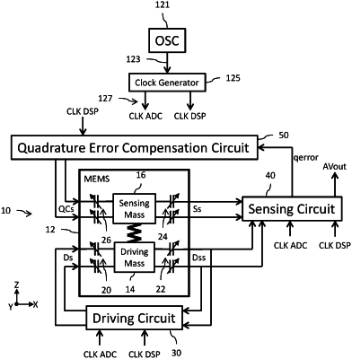
OG exemplary drawing
 
1. A method, comprising:
driving a driving mass of a microelectromechanical system (MEMS) gyroscope using a drive loop including a first analog-to-digital converter (ADC) circuit and a first digital signal processing (DSP) circuit;
wherein the driving mass is driven in a mechanical oscillation at a resonant drive frequency;
generating a system clock independent of and asynchronous to the resonant drive frequency;
generating a first clock and a second clock from the system clock;
clocking the first ADC circuit of the drive loop with the first clock; and
clocking the first DSP circuit of the drive loop with the second clock.