| CPC F24F 6/04 (2013.01) [A45B 23/00 (2013.01); F24F 9/00 (2013.01); A45B 2200/1036 (2013.01); F24F 2009/007 (2013.01)] | 20 Claims |

|
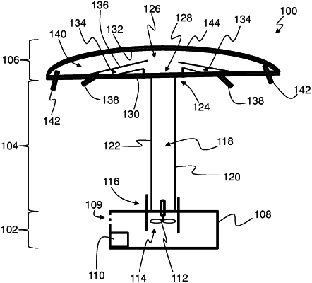
1. A cooling unit comprising:
a base having a housing with control components installed therein;
a cooling tower attached to the base at a first end of the cooling tower, the cooling tower having an inner flow path and an exterior surface;
a cooling unit water supply configured cool air of the cooling unit;
an air distribution system attached to the cooling tower at a second end of the cooling tower, the air distribution system including:
a first enclosure;
a second enclosure defining an air distribution chamber between the first and second enclosures;
a cover disposed on an exterior surface of the second enclosure; and
a plurality of dispersing apertures formed within the first enclosure to dispense air from the first enclosure of the air distribution system, wherein a first set of dispersing apertures of the plurality of dispersing apertures define a cool air dispenser and a second set of dispersing apertures of the plurality of dispersing apertures define a warm air dispenser, wherein the warm air dispenser is configured to generate a bounded cooled area in which the cool air dispenser dispenses cool air,
wherein the control components are configured to convey air through the base, the cooling tower, and the air distribution system to dispense air through the cool air dispenser and the warm air dispenser;
a heat exchange system operably connected to the cooling unit and configured to reject heat from water of the cooling unit water supply; and
a condensate evacuation system arranged to extract and dispose of excess water from the cooling unit water supply, wherein the condensate evacuation system is fluidly coupled to the heat exchange system.
|