| CPC F21V 5/007 (2013.01) [F21S 8/086 (2013.01); F21V 5/04 (2013.01); F21V 7/0091 (2013.01); F21W 2131/103 (2013.01); F21Y 2105/16 (2016.08); F21Y 2115/10 (2016.08)] | 14 Claims |

|
1. A light emitting device comprising:
at least one light source adapted for, in operation, emitting light source light,
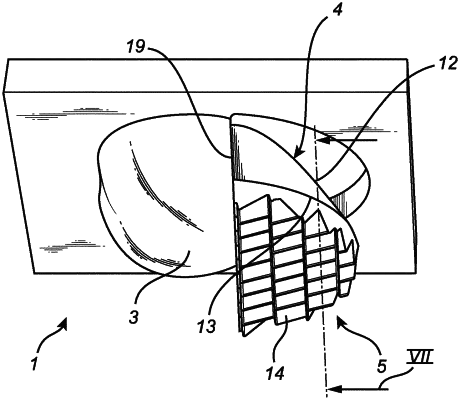
at least one free-shape refractive lens element configured to aim the light source light emitted by the at least one light source in a first direction towards a surface to be illuminated by the light emitting device, the free-shape refractive lens element comprising a first end adapted for facing in a direction towards the surface to be illuminated and a second end adapted for facing in a direction away from the surface to be illuminated,
at least one first TIR element, the first TIR element being a collimating TIR element configured to collimate and redirect light source light emitted from the at least one light source in a second direction away from the surface to be illuminated into first TIR element light propagating, parallel and in a downward direction, the first TIR element comprising a light incoupling surface and a light outcoupling surface, the light incoupling surface of the first TIR element being arranged at the second end of the free-shape refractive lens element, and
at least one second TIR element configured to redirect first TIR element light collimated and redirected by the first TIR element into second TIR element light propagating In a direction towards the surface to be illuminated and comprising an intensity distribution with two intensity peaks at wide angles that are aligned with the intensity peaks of refractive lens element light aimed by the free-shape refractive lens element, the at least one second TIR element being arranged at the light outcoupling surface of the first TIR element, the light outcoupling surface indicating the position where the first TIR element is ending and the second TIR element is beginning.
|