| CPC F16K 11/0853 (2013.01) [A61M 1/36 (2013.01); A61M 39/223 (2013.01); Y10T 137/86654 (2015.04); Y10T 137/86839 (2015.04)] | 7 Claims |

|
1. A flow path switching device, comprising:
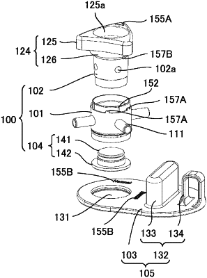
a body having a first port, a second port, a third port, and a fourth port which are provided at intervals of 90° and capable of being switched between a first state and a second state, the first state being a state in which the first port and the second port are connected and the third port and the fourth port are connected, and the second state being a state in which the first port and the fourth port are connected and the third port and the second port are connected;
a tube fixing portion configured to change directions in which at least part of the tubes are extended, and fix the tubes to hold the directions, wherein
a first tube connected to the first port, a second tube connected to the second port, a third tube connected to the third port, and a fourth tube connected to the fourth port; and
the tube fixing portion that fixes the tubes such that the first tube connected to the first port and the third tube connected to the third port are extended to a same side as viewed in plan and the second tube connected to the second port and the fourth tube connected to the fourth port are extended to a same side, which is an opposite side from the side to which the first tube and the third tube are extended, as viewed in plan, and
the tube fixing portion has one of following configurations:
a first tube holding portion that holds the second tube and the third tube to cross each other and a guide projection that guides the second tube and the third tube to the tube holding portion, the tube holding portion and the guide projection being provided on a plate having the body fixed thereto,
a second tube holding portion that is independent of the body and that holds the second tube and the third tube together such that the second tube and the third tube are extended in opposite directions, or
two of direction changing elements that provide with the second port and the third port and that guide the second tube and the third tube so that they are extended in opposite directions.
|