| CPC F16K 11/0787 (2013.01) [F16K 47/02 (2013.01); F16K 47/04 (2013.01); F16K 19/006 (2013.01); F16K 47/026 (2013.01)] | 9 Claims |

|
1. A single-lever cartridge for a sanitary faucet comprising:
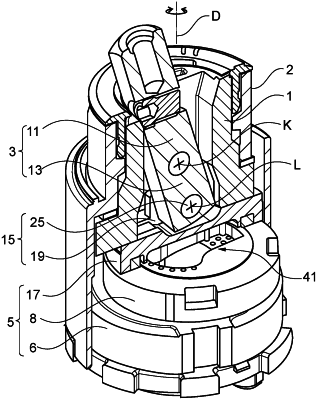
a swivel lever (3) for adjusting temperature and/or quantity of mixed water, and
a control disk arrangement (5) comprising:
a stationary control disk (6) disposed in a stationary manner in the single-lever cartridge, and
a dynamic control disk (8) displaceable by the swivel lever (3),
wherein the stationary control disk (6) has a cold-water inlet (29), a hot-water inlet (27), and a mixed-water outlet (31) formed therein,
wherein the dynamic control disk (8) has a recess (33) formed therein,
wherein the dynamic control disk (8) can be brought into different overlaps with the cold-water inlet (29), the hot-water inlet (27), and the mixed-water outlet (31) to adjust the temperature and/or quantity of mixed water routed from the mixed-water outlet (31) of the stationary control disk (6),
wherein the stationary control disk (6) has a sealing surface (35) and the dynamic control disk (8) has a sealing surface (37), the stationary control disk (6) and the dynamic control disk (8) being in sliding contact via the sealing surfaces (35, 37) thereof that are facing each other at a sealing plane (DE),
wherein mouths (39), which the sealing surface (37) of the dynamic control disk (8) of the cold-water inlet (29) and the hot-water inlet (27) can cover, are formed in the sealing surface (35) of the stationary control disk (6),
wherein the cartridge has a throttle element (41) as a separate component, which can be used to reduce a flow cross section of the mouths (39) of the cold-water inlet (29) and the hot-water inlet (27), for throttling hot-water flow and/or cold-water flow into the recess (33) of the dynamic control disk (8), and
wherein the throttle element (41) is cup-shaped, having a throttle bottom (43) and a shell (45) rising therefrom, wherein the throttle bottom (43) has throttle openings (55), which throttle bottom (43), at its bottom end facing the sealing surface (35) of the stationary control disk (6), is flush with the sealing plane (DE) and/or is in sliding contact with the sealing surface (35) of the stationary control disk (6),
wherein the control disk arrangement (5) has a slide plate (17) mounted in a stationary manner at the dynamic control disk (8), at which slide plate a bearing position (19) is formed for an axle connection (15) at the swivel lever (3), and in that the shell (45) of the throttle element (41) merges into an outwardly angled retaining flange (47) at its rim remote from the bottom, wherein the retaining flange (47) is secured between the dynamic control disk (8) and the slide plate (17), and in that the retaining flange (47) of the throttle element (41) is pressed against the dynamic control disk (8) by means of a spring (69).
|