| CPC F16F 9/49 (2013.01) [F16F 9/185 (2013.01); F16F 9/34 (2013.01)] | 8 Claims |

|
1. A damper comprising:
a pressure tube extending annularly about a damper axis;
a piston arranged in sliding engagement inside the pressure tube;
the piston dividing the pressure tube into a first working chamber and a second working chamber;
a piston rod coupled to the piston;
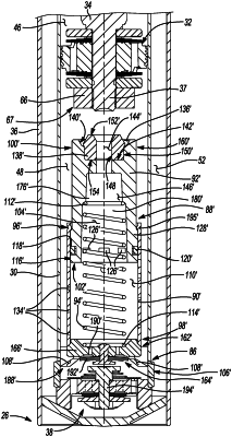
a hydraulic compression stop assembly positioned in the second working chamber, the hydraulic compression stop assembly including a sleeve, a plunger arranged in sliding engagement with the sleeve for movement between an extended position and a retracted position, and a biasing member that biases the plunger toward the extended position;
the plunger extending longitudinally between a first plunger end that is configured to contact at least one of the piston and the piston rod during a compression stroke and a second plunger end that is arranged in sliding engagement inside the sleeve; and
the first plunger end including a bumper cavity having a side wall and extending a cavity depth from an end face of the plunger, the bumper cavity being in receipt of a bumper made of a compliant material, the bumper including a bumper height greater than the cavity depth such that a portion of the bumper protrudes from the bumper cavity, wherein during the compression stroke, the portion of the bumper that protrudes from the cavity limits the maximum amount the bumper may be compressed before the side wall is loaded by the at least one of the piston and the piston rod.
|