| CPC F04D 29/448 (2013.01) [F04D 29/007 (2013.01); A47L 15/4225 (2013.01); F04D 29/588 (2013.01)] | 18 Claims |

|
1. A heat collecting pump, comprising:
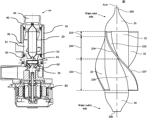
a flow guide member, comprising:
a flow guide body;
a first end portion disposed at a water inlet side of the flow guide body, wherein a radial size of the first end portion gradually and smoothly decreases in a direction away from the flow guide body, and the first end portion is smoothly connected to an end of the flow guide body; and
a second end portion disposed at a water outlet side of the flow guide body, wherein a radial size of the second end portion gradually and smoothly decreases in the direction away from the flow guide body, and the second end portion is smoothly connected to the other end of the flow guide body;
an inlet tube disposed at the water inlet side and an outlet end cap disposed at the water outlet side;
the inlet tube comprises a tube body and a first bracket, wherein the tube body defines an inlet channel, the first bracket is received in the inlet channel;
the outlet end cap comprises an end cap body and a second bracket, wherein the end cap body defines an outlet channel, the second bracket is received in the outlet channel;
the first end portion supports the first bracket, and the second end portion supports the second bracket; and
at least one flow guide blade, wherein the at least one flow guide blade is disposed on an outer peripheral wall of the flow guide body;
a heating member, disposed on a periphery of the flow guide member and spaced apart from the flow guide blade along a radial direction of the flow guide body;
wherein the flow guide blade is configured to enable water to flow along the outer peripheral wall of the flow guide body to form a first whirlwind flow and to further form a second whirlwind flow in a gap between the heating member and the flow guide blade;
a velocity direction of the first whirlwind flow is projected on a reference plane perpendicular to an axial direction of the flow guide body, generating a first projection;
a velocity direction of the second whirlwind flow is projected on the reference plane perpendicular to the axial direction of the flow guide body, generating a second projection;
the first projection and the second projection are in opposite directions; and
the second whirlwind flow is configured to remove bubbles gathered on the heating member.
|