| CPC F04C 29/028 (2013.01) [F04C 18/3441 (2013.01); F04C 18/356 (2013.01); F04C 29/023 (2013.01); F04C 2240/30 (2013.01); F04C 2240/56 (2013.01); F04C 2240/603 (2013.01)] | 16 Claims |

|
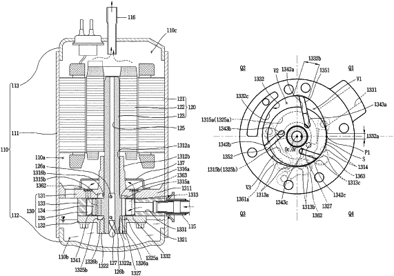
1. A rotary compressor, comprising:
a casing that defines an oil storage space therein;
a cylinder fixed in the casing to form a compression space;
a main bearing and a sub bearing disposed on both sides of the cylinder in an axial direction and having a main bearing hole and a sub bearing hole formed therethrough, respectively, in the axial direction;
a rotary shaft supported by being inserted through the main bearing hole and the sub bearing hole;
a roller disposed in the rotary shaft to be eccentric with respect to the compression space, and having at least one vane slot formed along an outer circumferential surface of the roller, and a back pressure chamber that communicates with an inner end of the at least one vane slot; and
at least one vane slidably inserted into the at least one vane slot and having a front end surface in contact with an inner circumferential surface of the cylinder to divide the compression space into a plurality of compression chambers, wherein an oil supply hole is formed through the main bearing or the sub bearing such that the back pressure chamber communicates with the oil storage space, wherein an oil through which oil stored in the oil storage space of the casing is suctioned is formed in a hollow shape inside of the rotary shaft, wherein a plurality of back pressure pockets that communicates with the oil so as to have different pressures is disposed in the main bearing or the sub bearing, wherein the plurality of back pressure pockets is disposed at predetermined distances in a circumferential direction in a surface facing an axial side surface of the roller, and wherein the oil supply hole is formed between the plurality of back pressure pockets such that at least a portion of the oil supply hole overlaps the back pressure chamber in the axial direction.
|