| CPC F02C 7/06 (2013.01) [F01D 25/18 (2013.01); F01D 25/20 (2013.01); F02C 7/32 (2013.01); F02C 7/36 (2013.01); F05D 2220/323 (2013.01); F05D 2240/54 (2013.01); F05D 2240/60 (2013.01); F05D 2260/40 (2013.01); F05D 2260/98 (2013.01)] | 10 Claims |

|
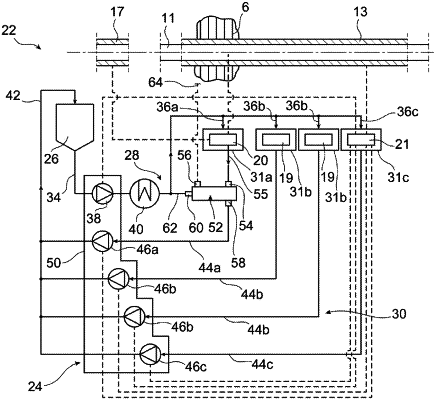
1. An assembly for an aircraft turbine engine, the assembly comprising a reduction gear for driving the fan of the turbine engine, as well as a lubrication system including:
a reduction gear enclosure, lubricated and containing the fan drive reduction gear;
a lubricant tank;
a lubricant supply circuit connecting the tank to the reduction gear enclosure, the supply circuit comprising a lubricant supply pump;
a lubricant recovery circuit connecting the reduction gear enclosure to the tank, the recovery circuit comprising a pump for recovering lubricant from the reduction gear enclosure,
wherein the lubricant recovery circuit includes a controlled lubricant dispenser, comprising:
a lubricant inlet communicating with a lubricant outlet of the reduction gear enclosure;
an air inlet; and
a dispenser outlet communicating with the recovery pump,
the controlled lubricant dispenser being configured to have several configurations, including:
a lubricant recovery configuration, in which the controlled lubricant dispenser communicates the lubricant inlet thereof with the dispenser outlet thereof, and prohibits the communication between the air inlet thereof and the dispenser outlet thereof; and
a lubricant blocking configuration in which the controlled lubricant dispenser communicates the air inlet thereof with the dispenser outlet thereof, and prohibits the communication between the lubricant inlet thereof and the dispenser outlet thereof.
|