| CPC F02C 3/14 (2013.01) [F01D 25/12 (2013.01); F02C 3/08 (2013.01); F02C 6/08 (2013.01)] | 16 Claims |

|
1. A turbine engine comprising:
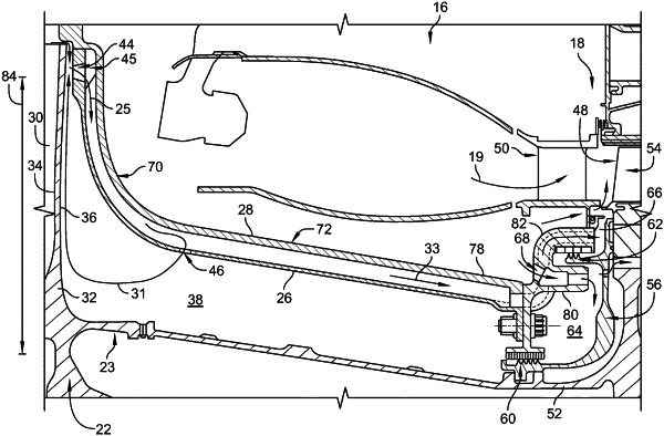
a centrifugal compressor including an impeller having an impeller disk and impeller blades that extend from the impeller disk, the impeller configured to rotate about an axis to produce compressor discharge air,
a combustor including an outer combustor case arranged around the axis and an inner combustor case arranged radially along an aft side of the impeller disk and extending axially aft relative to the axis, and
a turbine including a rotor assembly mounted for rotation about the axis and a turbine blade coupled with the rotor assembly for rotation therewith and defining an inner radial boundary of a gas path of the turbine, the rotor assembly including a body, a first sealing element coupled with the body and engaging the inner combustor case at a first location, and a second sealing element coupled with the body and engaging the inner combustor case at a second location to define an air plenum between the first sealing element and the second sealing element, the second sealing element fluidly separates the air plenum from a wheel cavity defined between the inner combustor case and the rotor assembly, and the wheel cavity opens into the gas path of the turbine,
wherein the inner combustor case is formed to include a cooling hole that extends through the inner combustor case and opens directly into the wheel cavity to direct a first portion of the compressor discharge air through the wheel cavity and into the gas path of the turbine,
wherein the inner combustor case is formed to include a bleed hole arranged radially inwardly from outlet tips of the impeller blades to allow a flow of bleed air that is bled from the compressor discharge air to pass through the bleed hole and along the inner combustor case, and
wherein the combustor further includes a manifold arranged along the inner combustor case and shaped to define a channel formed radially between the inner combustor case and the manifold and the flow of bleed air is conducted into the channel.
|