| CPC F01D 9/06 (2013.01) [F01D 17/105 (2013.01); F01D 17/145 (2013.01); F02C 6/08 (2013.01); F02C 9/18 (2013.01); F05D 2220/323 (2013.01); F05D 2240/14 (2013.01); F05D 2260/232 (2013.01); F05D 2260/605 (2013.01); F05D 2260/606 (2013.01)] | 18 Claims |

|
10. An aircraft, comprising:
a fuselage;
a wing attached to the fuselage; and
a gas turbine engine, the gas turbine engine comprising:
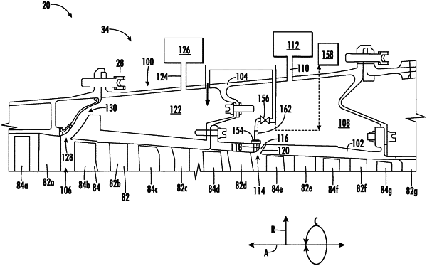
a compressor including an inner casing and an outer casing, the inner casing defining a primary flow path for airflow through the compressor, the inner casing and the outer casing defining a first bleed air cavity and a second bleed air cavity therebetween, the inner casing at least partially defining a first bleed air channel between the primary flow path and the first bleed air cavity to direct a portion of the airflow from the primary flow path into the first bleed air cavity, wherein the first bleed air channel is defined between a first wall and a second wall, the first wall being upstream from the second wall,
wherein the first wall includes a plurality of holes in fluid communication with the primary flow path and fluidly coupled to a suction manifold, wherein the suction manifold is disposed within the first bleed air cavity and is fluidly coupled to the second bleed air cavity, and wherein the plurality of holes is configured to energize a fluid boundary layer along the first wall; and
a valve disposed within the first bleed air cavity, wherein the valve is configured to control a flowrate of a portion of the airflow from the primary flow path, through the plurality of holes, into the suction manifold, and into the second bleed air cavity.
|