| CPC E05B 81/16 (2013.01) [E05B 77/02 (2013.01); E05B 81/06 (2013.01); E05B 81/14 (2013.01); E05B 81/90 (2013.01); E05B 83/36 (2013.01); E05B 85/26 (2013.01)] | 16 Claims |

|
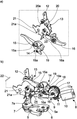
1. A motor vehicle lock comprising:
a lock latch configured to pivot about a geometric lock-latch axis and including a pawl configured to pivot about a geometric pawl axis,
wherein the lock latch is configured to be adjusted between an open position and a locked position,
wherein the pawl is configured to be adjusted to a lowered position, in which the pawl holds the lock latch in the locked position, and a raised position, in which the pawl releases the lock latch;
an adjusting arrangement;
an electric drive arrangement configured to move the adjusting arrangement in a first drive direction so the adjusting arrangement executes an opening movement from a starting position to adjust the adjusting arrangement such that the adjusting arrangement raises the pawl;
an actuating lever configured to pivot about a geometric actuating-lever axis; and
a clutch arrangement arranged between the actuating lever and the pawl and configured to shift between an engaging state, wherein during an actuation stroke of the actuation lever, the pawl is permitted to be raised by the actuation stroke, and a disengaging state, in which, the actuation stroke of the actuation lever is an idle stroke and does not permit raising of the pawl,
wherein adjustment of the adjusting arrangement and the opening movement of the electric drive arrangement shifts the clutch arrangement from the disengaging state to the engaging state,
wherein the electric drive arrangement is configured to move the adjusting arrangement from the starting position in a second drive direction, opposite the first drive direction, to execute an unlocking movement, and shift the clutch arrangement from the disengaging state to the engaging state, and
wherein the clutch arrangement includes a clutch lever configured to pivot about a geometric clutch-lever axis, wherein when the clutch arrangement is in the disengaging state and during the actuation stroke of the actuating lever, the clutch lever is in a disengaging position in which the clutch lever is out of coupling engagement with the actuating lever, wherein when the clutch arrangement is in the engaging state, the clutch lever is in an engaging position in which the clutch lever is in coupling engagement with the actuating lever or is configured to come into coupling engagement with the actuating lever during the actuation stroke of the actuating lever.
|